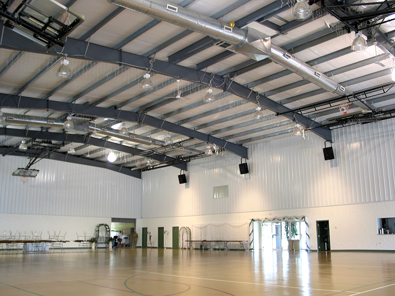
Steel Building Standard Features
Primary Framing
(Consisting of columns for sidewalls and rafters for roof.) Solid I-Beam construction for optimum strength. Material used is minimum 50,000 p.s.i. yield strength. (Some manufacturers use 35,000 p.s.i. yield strength material, which is not as strong.) By using a higher yield strength material, a smaller web can be utilized which means a space saving design. Frames are single bead; continuous submerged arc welded by automatic welding machines (this helps insure quality control). A factory primer coat is applied to help protect them during the erection process. End Wall Frames and Columns are either cold formed, mill-rolled or built-up “I” sections depending on design requirements.
Secondary Framing
Girts (in sidewall) & Purlins (in roof) are 8″ or 10″ to meet design requirements. Cold rolled Z-section, 13 to 16 ga. ASTM A-570, 55,000 p.s.i. yield material is used to provide maximum strength. Bypass girt system overlaps at sidewall columns forming a continuous “beam” for extra strength. Purlins are top-mounted on the rafter with a varied lap of 2′ to 6′ for strength and cost savings in erection labor. Maximum purlin spacing is 5′ on center. Eave Strut is a cold-formed C-Section that is rolled for the appropriate roof pitch, to help insure weather tightness at the eave. Sheeting angle is a continuous sheeting angle supplied for the attachment of the sheeting at the rake of the building for ease of installation. Base angle is a continuous angle, supplied for the attachment of the base of the sheeting to the concrete. It is attached to the concrete with ram-sets or equivalent anchors by others. Bracing diagonal rod or cable bracing may be supplied for roof and walls to remove longitudinal load from the structure. Angle Flange Bracing is provided for the connection of the rigid frame to the purlins and girts. This ensures that allowable compression levels are adequate for any combination of loadings. Purlin bridging angles may be provided at each mid-bay to assure consistent purlin spacing and stiffening.
Sheeting
80,000 p.s.i. yield material standard. Some manufacturers use a lower yield strength material, which is less resistant to damage from hail or other impacts. All Coil Steel with Galvalume coating standard (1.25oz-hot dipped) on each side helps prevent deterioration of the steel sheeting. Deeper High-Rib with more frequent corrugations, provides extra strength. Optional Semi-Concealed Panel-“Shadow Line” configuration is available for walls, mansard systems, soffit material, etc…, to add an aesthetic appeal to your building.
Fasteners
Structural Bolts meet requirements of ASTM Standards. A-325 for primary frame connections. A-307 for secondary framing. Self-Drilling and Self-Tapping Fasteners are pre-assembled with neoprene washers and metal caps to help insure weather tightness.
Closures
Closed Cell Neoprene Strips with self-adhesive backing used to help seal building. Located at rake & roofline of building to help provide weather tightness. Optional eave and base closures may be added. Pre-formed shapes to match panel configuration providing a tighter seal. 1 ½” Sheeting Notch at base of concrete where panel sits is designed into every building. Sheeting notch provides an air infiltration stop on blank insulated buildings.
Sealants
Sealant for roof sidelaps, endlaps and flashing at gable is provided to help insure weather tightness. Nominal 3/8″ x 1/8″ thick pressure sensitive tape sealant for ease of installation.
Ridge Cap
Preformed High-Rib Ridge Cap Panel matches the slope and profile of adjoining roof panels to help insure constant alignment and weather tightness. Long Overlap is provided to help prevent water from siphoning into the building.
Trim And Flashing
Trimming at rake (gable) corners and eaves is provided for all buildings with standard trim material for a finished look. This is also an additional deterrent to moisture, insects and dirt getting into building.
Plans And Drawing
Anchor Bolt Setting Plan, building reactions for foundation design, Erection Manual and Engineer Letter of Certification are provided shortly after receipt of deposit on building. General Building Manual and erection drawing provide step by step instructions for assembly. Engineer Certified Erection Drawings, including wall and roof framing diagrams, cross sections, sheeting and flashing details are provided. These drawings show clearly the proper erection and assembly of all building components. Part Numbers Are Placed On Each Component (other than screws). These part numbers coincide with a detailed listing contained in the construction drawings and shipping list to help with assembly of the building.


